ADDING CIRCUITS

We therefore introduce the two fundamental functional blocks which are:
• The binary half-adder HA (Half Adder) without input carry;
• The binary adder FA (Full Adder) with input carry.
BINARY ADDER, BINARY HALF ADDER HALF ADDER
In binary compared to the decimal system the sum is much simpler, the rules to follow for the binary sum are summarized in the following table.
Figure 1.
|
A |
B |
Y |
R |
|
0 |
0 |
0 |
|
|
0 |
1 |
1 |
|
|
1 |
0 |
1 |
|
|
1 |
1 |
0 |
1 |
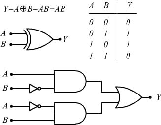
As can be seen, the Y output, apart from the carryover that I indicated with R, corresponds to the output of an XOR logic gate.
Y= A ⊕ B = A̅B+AB̅

FROM THE TRUTH TABLE TO THE CIRCUIT
From the truth table we get the second circuit built with elementary gates. Now we have to consider the carryover which, as we can see from the table summarizing the rules of binary addition (Figure 1), occurs only when both input bits are equal to 1, which makes us think of a logic AND gate.

BLOCK DIAGRAM OF A HALF ADDER

BINARY ADDER, FULL ADDER
The created device is called half-adder this name derives from the fact that to obtain the complete sum (full-adder) between two numbers of several digits, in addition to the bits of the same order, it is also necessary to add the carry eventually obtained from the two bits of immediately lower order. For this reason the full circuit -adder comes with three inputs and two outputs. The two inputs consist of the two bits A n and B n to be added and of the carry C i possibly obtained from the sum of the two bits
A n-1 and B n-1 .
THE OUTPUTS
The two outputs are made up of the sum bit of the three inputs and the possible carry C o to be sent to the next full-adder. The logic symbol, truth table, and circuit diagram of a full-adder is shown below.

|
INPUTS |
OUTPUT |
|||
|
A |
B |
CI |
S |
C0 |
|
0 |
0 |
0 |
0 |
0 |
|
0 |
0 |
1 |
1 |
0 |
|
0 |
1 |
0 |
1 |
0 |
|
0 |
1 |
1 |
0 |
1 |
|
1 |
0 |
0 |
1 |
0 |
|
1 |
0 |
1 |
0 |
1 |
|
1 |
1 |
0 |
0 |
1 |
|
1 |
1 |
1 |
1 |
1 |

From the truth table, it is possible to deduce the add-and-carry logic function performed by this combinatorial circuit.


When you want to add numbers of several bits each, the simplest method is to create a parallel adder as shown below, cascading as many FAs (full-adders) as there are bits of each binary number to be added.

If by hypothesis we use nibbles (4 bits) the four bits of each number are presented simultaneously at the input of the full-adder and the sum is performed if there is no carry. In the worst case, however, in which each sum corresponds to a carry, this bit will translate from the first HA to all the other FAs up to the last.
4 BIT ADDING CIRCUIT

FULL ADDER DETAILS
The full-adder or complete adder It is a logic circuit featuring three inputs and two outputs. Its functionality is to perform a sum between two numbers expressed in binary format with a one-bit word length. It is a fundamental component of digital electronics because, suitably connected with other full-adders and logic gates, it can give rise to the ALU ( Arithmetic Logic Unit ) processing units of the processors. Full-adders are the foundation upon which the construction of simple calculators is based. The full-adder consists of the set of two half-adders and an OR logic gate, suitably connected (Figure on the right).
In binary logic it does this simple operation:
A + B + Ci = S + Co
where A and B are the operands, Ci the input carry (C → carry ) of the previous sum and S and Co are the output sum and carry. Each variable is a bit (0 or 1). The two bits to be added and any carry bit are entered as input; the sum and the carryover are provided in output. For example, if we input the values 1 1 0 (1st number, 2nd number, carry), the component will return the value 0 with carry 1 (corresponding to the value 10 in binary basis).


FULL ADDER A n BIT
The structure with the carry on input exists in order to possibly connect an “n” full-adder number in cascade in order to obtain “n” bit full-adder.


Leave A Comment