MULTIPLEXER DEFINITION
 The Multiplexer, also called MUX , is a combinatorial digital circuit able to select one of 2n input lines (data lines) and to report the values of this line on a single output. For this purpose, in general, the circuit has, in addition to the data inputs, also n selection inputs. The figure below shows the simple block diagram of a MUX with 2 data inputs and 1 selection input. AND’ a data line selector able to select different input signals both analog and digital. Once selected, the signals are collected and sent to a single output line. They are mainly used to increase the amount of data that can be transmitted through a network in certain time and bandwidth quotas, therefore the term is used both in electronics and in telecommunications at the same time.
CIRCUIT WITH TWO INPUTS

Y=AP + BP̅
Let’s see how it works. If P=0 the lowest AND gate has a high logic output (1) therefore the data present in B is transferred. If P=1 the highest AND gate has a high output (logic 1) therefore input A and its associated logic value are transferred to Y.
USE IN THE ELECTRONIC FIELD
In electronics, the term can refer to a type of integrated circuit, or to a particular complete piece of equipment. In the first case, a multiplexer (also called selector ) is a device capable of selecting a single electrical signal among several input signals based on the value of the selection inputs . There are multiplexers for both digital signals and analog signals ( amux ). For example, a two-input multiplexer is a simple logic gate whose output Y takes the value of either input A or B based on the value of the third select input S. The Boolean equation is:
- Y=AS̅ + BS
Which can be expressed by the following truth table: This truth table shows that when the selector equals “0”, then Y is connected to A; while when the selector equals “1”, Y is dependent on B.
TRUTH TABLE

MULTIPLEXER SCHEME

MULTIPLEXER WITH 4 INPUTS


The logic function that realizes this circuit will be:
Y=AP̅ 1 P̅ 2 + BP̅ 1 P 2 + CP 1 P̅ 2 + DP 1 P 2
OPERATION:
When P1 and P2 are at zero logic level on the output of the first AND we will have the logic signal of A because the other ANDs are at low logic level. The same goes for the other entrances.
MULTIPLEXERS AND LOGICAL FUNCTIONS
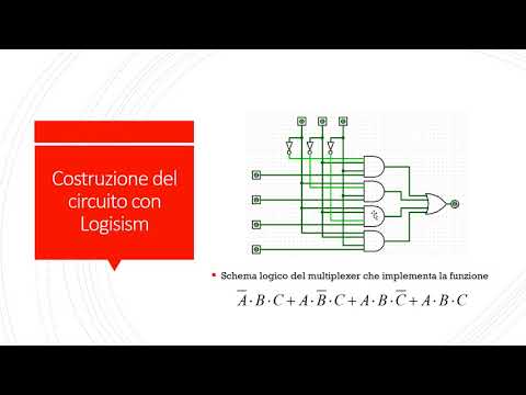
One of the main uses of the MUX is the realization of logic functions. Suppose we have the following truth table.

Y=A̅B̅C + A̅BC̅ + AB̅C̅ + ABC
To understand how to use the MULTIPLEXER, use the following table.
|
INPUTS |
OUTPUT |
||
|
A |
B |
C |
Y |
|
P0 |
P 1 |
P 2 |
|
|
0 |
0 |
0 |
0=X 0 |
|
0 |
0 |
1 |
1=X 1 |
|
0 |
1 |
0 |
1=X 2 |
|
0 |
1 |
1 |
0=X 3 |
|
1 |
0 |
0 |
1=X 4 |
|
1 |
0 |
1 |
0=X 5 |
|
1 |
1 |
0 |
0=X 6 |
|
1 |
1 |
1 |
1=X 7 |
In this case we have to create a circuit with 8 data inputs and 3 selection inputs.

Y = X0 P̅2 P̅1 P̅0 + X1 P̅2 P̅1 p0 + X2 P̅2 p1 P̅0 + X3 P̅2 p1 p0 + X4 p2 P̅1 P̅0 + X5 p2 P̅1 p0 + X6 p2 p1 P̅0 + X7 p2 p1 p0
having set X 0 =X 3 =X 5 =X 6 =0 and X 1 =X 2 =X 4 =X 7 =1 we reduce to:
Y = X1 P̅2 P̅1 p0 + X2 P̅2 p1 P̅0 + X4 p2 P̅1 P̅0 + X7 p2 p1 p0
Y = P̅ 2 P̅ 1 P 0 + P̅ 2 P 1 P̅ 0 + P 2 P̅ 1 P̅ 0 + P 2 P 1 P 0
Y = A̅B̅C+ A̅BC̅ + AB̅C̅ + ABC
LINKS TO PREVIOUS POSTS ON DIGITAL ELECTRONICS
FURTHER LINKS
INTEGRATED CIRCUITS
TTL 74150: 16-input mux
TTL 74151: 8-input mux
TTL 74153: two 4-input muxes

Leave A Comment